


 LCD (Liquid Crystal Display) has low power consumption, high contrast, density of information
and a lot of advantages compared to other display devices.
Especially, many LCDs used in calculators, clocks or watches and other electronic home appliances
have special pictgrams on their screen
to achieve comprehensive user interface in smaller display area.
If I can re-use these LCD devices from old machines,
they must be providing my DIY projects with more flexible user interface.
LCD (Liquid Crystal Display) has low power consumption, high contrast, density of information
and a lot of advantages compared to other display devices.
Especially, many LCDs used in calculators, clocks or watches and other electronic home appliances
have special pictgrams on their screen
to achieve comprehensive user interface in smaller display area.
If I can re-use these LCD devices from old machines,
they must be providing my DIY projects with more flexible user interface.
This article presents my small experiment to find how I can control segment-type LCD by MCU GPIO and resistors.
About LCD
How LCD operates
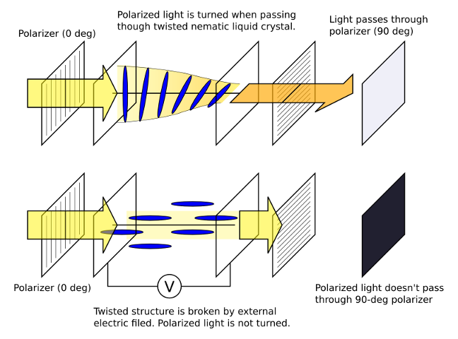
Operation of Twisted Nematic LCD (click to enlarge)
There are different types of LCD in their operation. This article will talk about passive (reflective) LCD, many of which are "twisted nematic" or "super-twisted nematic". They have simple structure where liquid crystal is packed between two parallel flat glasses with transparent electrodes on inner surfaces. When an appropriate voltage is applyed between two electrodes, induced electric filed across the liquid crystal changes molecule alignments and optical property characteristics to display information.
(Note) Although liquid crystal itself doesn't emit light, in this article I will use the terms of "lit" or "unlit" for convenience. "Lit" means that a segment shape is visible due to optical change induced by electric input. "Unlit" is deactivated state in which a segment is not visible.
How to drive LCD
Segment-type LCD is driven by control of voltage between common electrodes and segment electrodes to have desired segments lit or unlit. The applied voltage must be alternating without dc component to prevent deterioration of liquid crystal caused by eletrolysis. In common operation 30 to 150 Hz frequency is used.
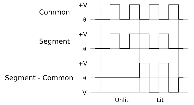
In static drive, for example, segments are lit/unlit by applying controlled voltage shown in the figure. Lit segments have ± V of difference against the common electrode while unlit segments have none.
Just like displaying multiple number figures by 7-segment LED, the more digits you have, the more pins you will need to control. To reduce the number of wirings and ports, most of multiple digits are driven dynamically with three or more common backplane electrodes.
In dynamic drive, we need a bit complicated waveform to control.
First, we apply different phases of alternating voltage to different common electrodes, and then, by applying voltage to a segment with carefully controlled timing, we can light it if its volatage difference from the common electrode is high enough, and turn off if low. If you can use some LCD controller ICs specialized in this function, they may employ multiple divided voltages to provide higher contrast by bigger difference of supplied voltage between lit and unlit conditions.
Duty and bias
The number of time division is called "duty", and the number of volatege division is indicated as "bias" as technical terms in LCD controllers. Datasheet for LCD controllers or MCU-integrated LCDC feature (like ATMega169) may present the waveforms with different configurations of duty and bias. The following figure shows the waveform exmaples of "1/3 duty, 1/2 bias" and "1/3 duty, 1/3 bias" configurations, which I experimented.
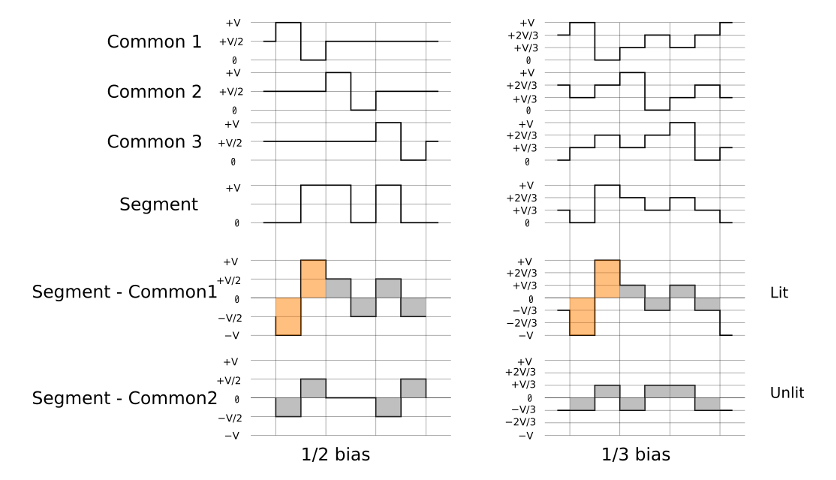
The waveforms may appear a bit complicated, but you will understand easily by checking each phase how much volatage difference will be applied when a segment is lit or unlit. Either configuration will supply larger power to lit segments and smaller power to unlit segments.
Output of bias voltages
For simple circuitry without usage of amplifiers or analog swithes, the experimented hardware employs following resistor networks.
- Analog voltage output (1/2 bias) by AVR GPIO
- Analog voltage output (1/3 bias) by AVR GPIO
1/2-bias configuration needs three volatage states of "0", "1/2" and "1". Because LCD has very high impedance and needs little drive current, we can obtain 1/2 volatage at a GPIO pin in the figure if we set the port as 3-state.
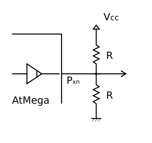
Resistor network for 1/2 bias
| PORTxn | DDxn | Output |
|---|---|---|
| 0 | 1 | 0 (Low) |
| 1 | 1 | 1 (High) | 0 | 0 | 1/2 (3-state) |
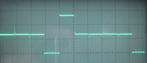
Observed waveform (1/2 bias)
1/3-bias configuration requires four states of "0", "1/3", "2/3" and "1". By using pull-up feature individually equipped to every AVR port pin, the following resistor network will provide "1/3" and "2/3" voltages.
According to the datasheet, the pull-up resistor value Rpu has a range of 20kΩ to 50kΩ. In my design it is estimated as approximately 30kΩ.
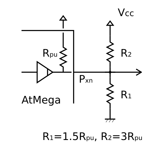
Resistor network for 1/3 bias
| PORTxn | DDxn | Output |
|---|---|---|
| 0 | 1 | 0 (Low) |
| 1 | 1 | 1 (High) | 0 | 0 | 1/3 (3-state) | 1 | 0 | 2/3 (Weak pull up) |
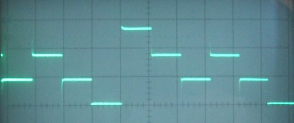
Observed waveform (1/3 bias)
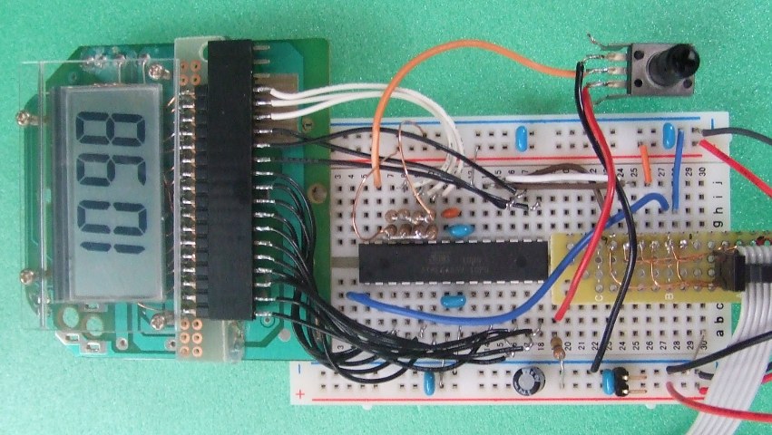
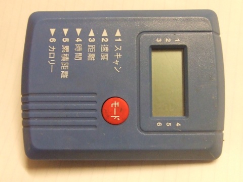
LCD for the experiment
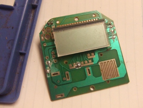
Junk LCD breakout
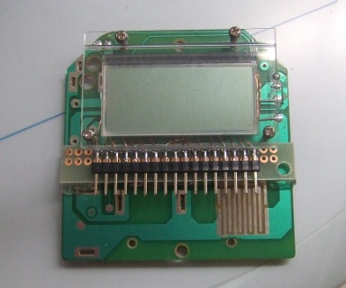
LCD for my hardware is a component extracted from a junk device with its detail unknown. Of course I cannot connect it in a straigt way, so I made up this breakout board by cutting connections between its LCD and controller IC, adding a new connector for direct wiring to the display electrodes. In addition, a small transparent plastic plate is fixed by screws so that the LCD and PCB are firmly contacted to the anisotropic conductive rubber piece (elastic material which connects the display and PCB, it conducts only in a particluar direction). When placing the LCD glass plate on the rubber piece, it is important to adjust the electrode positions so that they are correctly connected to the pads on PCB.
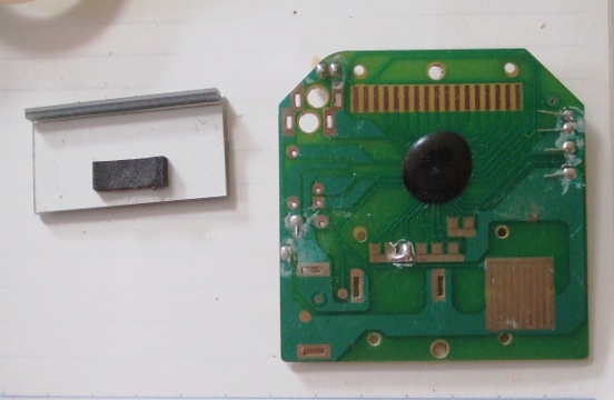
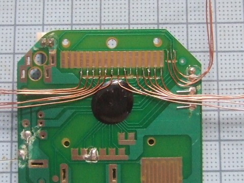
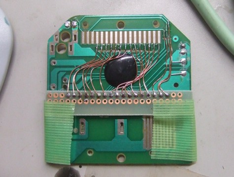
Note that the junk device I got had its controller on PCB (COB; chip on board) and I could add wires for direct connection to the LCD. The method shown above is not applicable to other types of LCD that has a controller on the glass plate (COG; chip on glass), or on the flexible film wire (COF; chip on film).
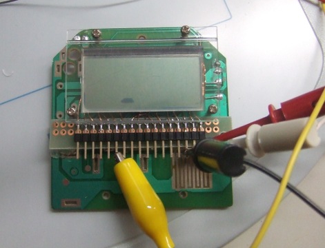
Find out electrode connections
We can look for electrode connections by looking for lit segments when one by one applying square wave of 1 to 3 volt and 100 Hz frequency. If a segment is lit, the seleted two electrodes must be a common and a segment. By repeating the steps, we can check what pins are connected to what segments/commons, and find the entire connection.
Sometimes a segment may be lit without applying voltage, or too many segments are lit at the same time. This is due to high impedance of LCD which is susceptible to external noise or electrostatic charge. It can be eliminated by pulling down all pins to GND through resistors, for example, 10kΩ.
Find LCD connections
To find connections, other clues may be useful. You may be able to see a shade of electrodes or wiring on the glass by looking at the display in a particluar direction. Some displays have markings on its glass or PCB.
Following illustration shows the pin connection of my LCD.
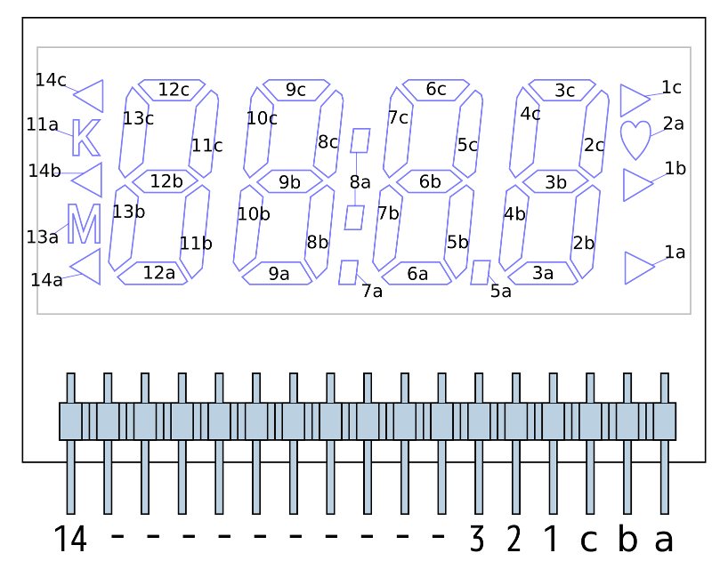
LCD connection
Target hardware
Schematic
The main MCU is ATMega88. It runs by the internal RC oscillator at 8MHz (no prescaling, CKDIV8 = OFF). Most of its ports are directly conncected to the LCD.
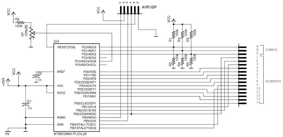
Schematic for 1/2 bias, 3 common configuration
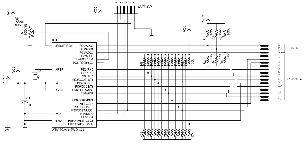
Schematic for 1/3 bias, 3 common configuration
For easy wiring on a bread board, the port configurations are like following. This configuration can be changed by software, so I can choose the easiest GPIO pins to connect.
| Port pin | LCD electrode |
|---|---|
| PB0 | segment 14 |
| PB1 | segment 3 |
| PB2 | segment 2 |
| PB3 | segment 1 |
| PB6 | segment 9 |
| PB7 | segment 10 |
| PC0 | common C |
| PC1 | common B |
| PC2 | common A |
| PD0 | segment 4 |
| PD1 | segment 5 |
| PD2 | segment 6 |
| PD3 | segment 7 |
| PD4 | segment 8 |
| PD5 | segment 11 |
| PD6 | segment 12 |
| PD7 | segment 13 |
An analog voltage divided by a variable resistor is inputted to ADC4 pin. The input is used for testing to show digit numbers although it is not directly related with LCD contorl. A capacitor connected to AREF pin is a noise suppressor for internal 1.1 volt reference. However, more careful design is required for serious measurement, for example, separation of analog circuit by inserting filter before AVCC.
Target hardware (1/2 bias)
Software
Source code
The source code follows. It is compiled by avr-gcc.
Source code 1: lcd_test_main.c (for build project, waveform tables are necessary. shown later)Overview of software
- int8_t lcd_segments[14] : buffer for segments
- const int8_t lookup[24] : port lookup table
- 0: unused
- (positive value): the number of segment
- (negative value): the number of common
- void output_voltage(int bit, int voltage)
- ISR (TIMER0_OVF_vect) : Timer 0 interrupt
- void lcd_segment_on(int segline, int bit)
- void lcd_segment_off(int segline, int bit)
- void lcd_put_segments(int8_t segline, int8_t mask, int8_t pattern)
- void lcd_print_number(int8_t segline, int8_t num)
- ISR(ADC_vect) : ADC interrupt
- main function
The array keeps segment lit/unlit conditions for each bit. To simplify software, only lower three bits in each byte are used.
The constant table defines port B, C and D connections to the LCD.
The meaning of values are :
The function make bias voltage output to the given segment bit.
In the Timer0 interrupt, the software looks up each port bit to find its assignment on segment or common electrode. From the phase when the interrupt occurs and the lit condition of the segments, it selects appropriate waveform and generates voltage output on port pins.
The data structure is designed to make it easier to change port or waveform configurations. With very small change, this software will be usable to different number of common/segment LCD.
They are utility functions to control LCD segments, or print out numbers.
A/D conversion is automatically started by Timer1 overflow (approximately every 0.5 sec). When ADC completes a conversion, ADC interrupt occurs and the 10-bit result is stored into analog_in variable.
In main function, the software take in analog input and generates bit patters for lit segments on the array.
ADC4 input is converted with reference of internal 1.1 volt. To get digit number, the actual voltage value must be calculated by the following formula.
The final voltage value is expressed in 4 decimal digits to display on LCD (0000〜1098mV). When I turn the variable resistor, I can observe change of digits on LCD.
Experiement
Waveform selection
Different waveforms are used in 1/2 bias and 1/3 bias. Each waveform is generated from different source code. Either of the following two lcd_waveform.c should be used.
Source code 2 : lcd_waveform.c (for 1/2 bias)
The waveforms from each tables are shown in the following pictures.
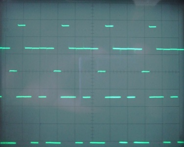
1/2 bias waveform (5mS/div, 1V/div)
Upper: common / Lower: segment
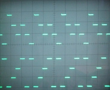
1/3 bias waveform (5mS/div, 1V/div)
Upper: common / Lower: segment
Experiment result
- Difference of display condition for each bias
- Power consumption (Vcc = 2.3V)
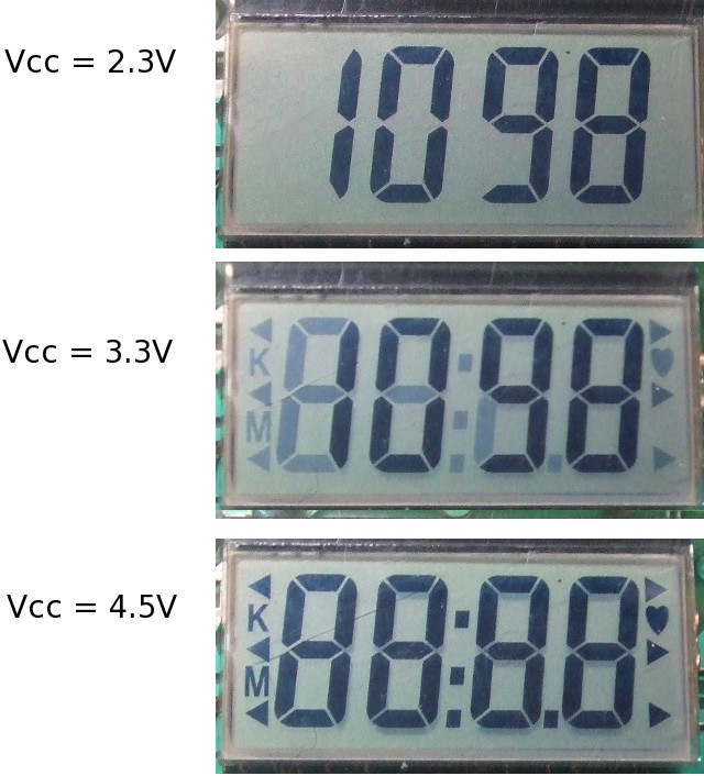
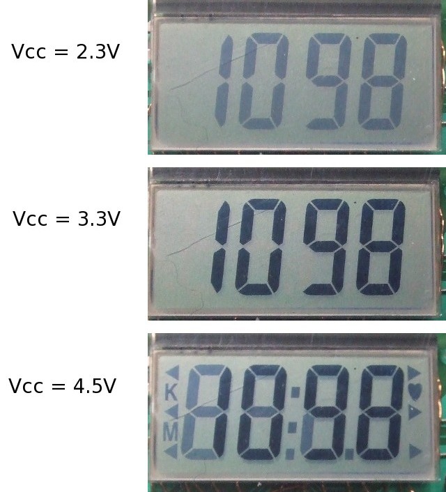
The following pictures show the observed display variation when I supplied different Vcc settings for 1/2 bias and 1/3 bias.
Result (1/2 bias)
Result (1/3 bias)
In 1/2 bias configuration, the digits are clearly displayed in lower (2.3 volt) Vcc because larger power is supplied on lit condition. However, in higher Vcc, its contrast gets worse as unlit segments are also turned on.
In 1/3 bias configuration, the display cannot achieve good contrast at lower Vcc, but it keeps rather good condition at higher Vcc. The change of bias configuration affects the range of voltage for good contrast.
| 1/2 bias | 3.52mA |
| 1/3 bias | 3.93mA |
As most of the ports are connected to Vcc or GND throug resistors, 1/3 configuration has larger power cunsumption. In its design a certain amount of current flows from Vcc to GND even when all LCD electrodes are inactive. For an application that this current consumption will be an issue, there need to be some additional circuit to shut down power supply to the entire resistor network before MCU gets into sleep mode.
Summary, and issues to be solved.
About LCD control by plain AVR GPIO
Without an external LCD controller, the total number of parts will be reduced. If I can find a small LCD, I may be able to make very small DIY device. Both 1/2 and 1/3 bias configurations are very good in display quality, and the choice of bias will bring wide range of LCD selection.
Also, by using AVR serial interface (SPI, I2C etc), I can build up original LCD module to communicate with other MCU.
Other issues to be solved
The software in the experiment is not efficient in performance, memory usage and code size. Especially its timer0 interrupt routine has too many things to be done in short time, and I had to speed up ATMega by supplying 8MHz (CKDIV8 = off). Withoug losing its flexibility, I would like to improve the software for less CPU power usage.
Finally
Before starting this experiment, I imagined more distinctive difference between the two bias configurations. Actually the difference is not so big maybe because the numuber of multiplexing is only three. LCD with larger number of multiplexing, like dot-matrix type, may have different results. One AVR GPIO pin cannot provide more than four states (1/3 bias), but the number of duty (time division) can be increased.
Passive (reflective) LCD consumes little power and has high density of display information. Only considering its functions and features, it would be very good for small DIY gadgets. However, most of the LCD devices that embedded in consumer products are custome-made parts and hardly available in electronic parts shops. By using the technique in the article, I would like to find good LCD parts widely available in the junk market.
Reference
I appreciate very much the following pages and their authors. They gave me a lot of helpful information to write this article. Thank you!
- Ojisan Koubou LC meter (using calculator's LCD)
- Application Notes (LXD, LLC)
An article of DIY LC meter which uses calculator's LCD as its display. The latter sections explain how to control LCD by AVR, that gave me the main motivation for reuse of junk LCD. The author also writes other interesting articles, very helpful to me.
Link:
http://ojisankoubou.web.fc2.com/lc-meter/index.html
(English transltion is available from the top page)
http://ojisankoubou.web.fc2.com/index.html
Techinical documents created by LXD, LLC, an LCD and controller manufacturer. The pages provide extensive information about LCD technologies and applications. Especially, multiplexing technique is clearly explained with its theoretical background. Very helpful.