


Experiment: AVR SPI (to control dot-matrix LED)
 Small microcontrollers may often have less general purpose ports than you need, especially when making circuits that require many inputs and outputs.
It is an easy and good solution to change the device to other with more ports, but in some cases you may be able to increase the number of ports by using serial-to-parallel converter.
Small microcontrollers may often have less general purpose ports than you need, especially when making circuits that require many inputs and outputs.
It is an easy and good solution to change the device to other with more ports, but in some cases you may be able to increase the number of ports by using serial-to-parallel converter.
This article describes my small experiment to expand Atmel AVR ports by using SPI and standard logic IC's, and control dot-matrix LED.
About SPI
Many microcontrollers have a limited number of general purpose ports and some of them have a serial bus to transfer data from/to peripheral devices. SPI, or serial peripheral interface is one of the most popular serial buses. SPI employs three signals and select lines to send/receive data. Its data transfer is synchronous communication based on the clock signal, and has relatively simple hardware system. This experiment would help me understand the basic mechanism of SPI, by using Atmel AVR ATmega88 as an SPI master and some generic logic IC's as a slave device.
Excerpt from BOM
- 74HC595
- Dot-matrix LED display
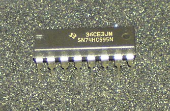
74HC595 (HC595) is an eight-bit serial-to-parallel shift register and latch. A lot of manufacturers release compatible devices and I used this datasheet for the experiment. →Texas Instruments SN74H595 (ti.com)
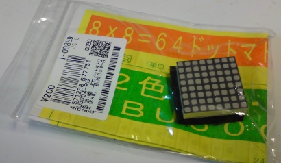
The experiment uses a dot-matrix LED display to observe SPI operation, which converts serial data to parallel output. I bought an 8x8 red-and-green LED at Akizuki denshi, a junk electronic parts shop, popular in Tokyo. It was said "BU5004-RG" made by Stanley and had a small printed datasheet. According to the datasheet, it has common cathodes, red LED's with Vf = 1.7V(typ), and green LED's with Vf = 2.2V(typ).
The following is a library file I made up to draw schematic with CadSoft Eagle.
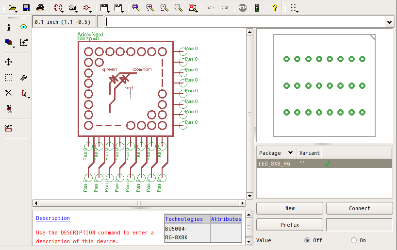
(8x8 red-and-green LED, Eagle library)
(You can download the library file from this url; → "8x8LED.lbr" made with Eagle 5.10.0 Linux)
Now let's consider how to control this graphic LED display. Simply counting, it will need ports for eight anodes of red LED, eight anodes of green LED, and eight common cathodes; 24 bits in total. Small sized MCU may have difficulty in driving the display because it has a small number of ports. In the article, I connect three HC595 in series to form a 24-bit shift register and drive it by SPI bus.
Design SPI peripheral
SPI operation
The picture below shows the basic mechanism of SPI.
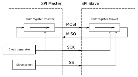
A conceptual sketch of SPI
An SPI master and a slave have shift registers connected to each other through MOSI (master-out-slave-in) and MISO (master-in-slave-out) signals.
The master and the slave exchange data by loading data onto the shift register and giving clock signal to the SCK line.
An SPI slave device can be built with simple circuits. A "Serial-in/Parallel-out" output port or a "Parallel-in/Serial-out" input port usually consists of control logic for SCK and SS signals, shift registers and latch circuit.
Connect HC595 to SPI
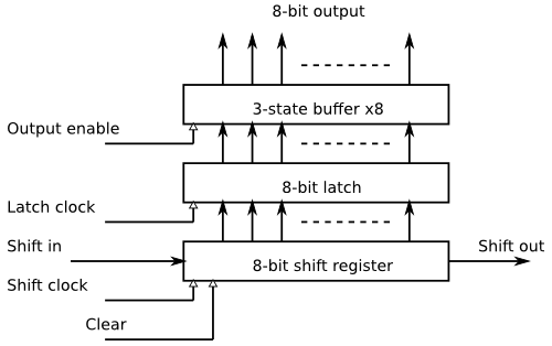
74HC595 has an 8-bit shift register and an 8-bit latch in it, and suitable for conversion from serial input to parallel output (see the block diagram). Its shift register and latch are synchronous logic circuits with independent clock signals, and each of them are clocked by a positive edge. The clear input of shift register and the output enable of latch are designed to work asynchronously (regardless of clock). For detail operation, please see the transition table below.
| Input | Operation | ||||
|---|---|---|---|---|---|
| SER | SRCLK | /CLR | RCLK | /OE | |
| X | X | X | X | H | Qa ... Qh pins are in 3-state |
| X | X | X | X | L | Qa ... Qh pins are driven to the latched value |
| X | X | L | X | X | Clear shift register bits |
| L | ↑ | H | X | X | Shift, with the first bit as 0 |
| H | ↑ | H | X | X | Shift, with the first bit as 1 |
| X | X | X | ↑ | X | Latch shift register bits |
Considering the timing of state changes, we can design the connection and settings like following.
First, let's see MOSI, the master output. HC595 clocks with a positive edge of shift clock. When a new bit value is set up on the serial input and a positive edge comes in, HC595 takes the bit value into its shift register. Therefore if you connect MOSI to SER input and SCK to SRCLK, you should make its clock settings like
- Falling edge as leading edge: Setup of MOSI connected to SER.
- Rising edge as trailing edge: Shift HC595's shift register
Next, after HC595's shift register sequentially takes in 8 bits, you should set the latch clock signal to high so that HC595 can capture the shift register bits into the latch logic. The usual design of /SS line (High = "inactive", Low = "selected") will work fine if it is connected to RCLK clock input. Note that this setting will give the first bit value to Qh output, and the last bit value to Qa output, meaning "Qh = MSB / Qa = LSB" if MSB is sent out first.
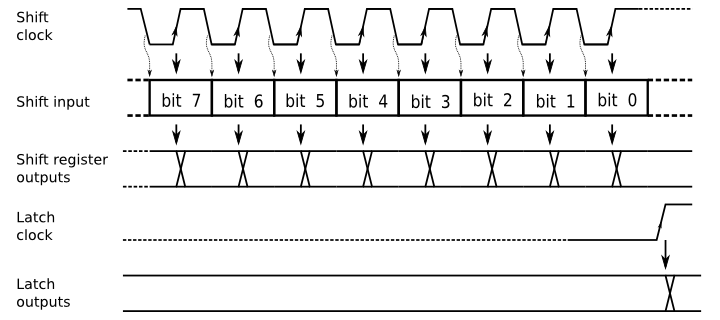
HC595 timing diagram
From that consideration, the following connection between ATmega88 SPI and HC595 will form an 8-bit SPI parallel output.
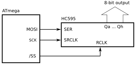
AVR SPI and HC595 wiring (8 bit)
You should set up AVR(ATmega) SPI like,
- Clock mode: Mode 3 (leading edge is falling: latch, trailing edge is rising: shift)
- SPI master operation, /SS as output
- Data order: MSB first (this depends on your situation. either order will work)
You can increase the number of output bits to 16 bits or 24 bits by a series connection of HC595's, between each HC595's serial outputs (Qh') and next serial inputs (SER). (See the following diagram, or target schematic shown later)
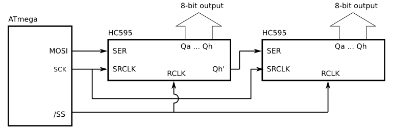
AVR SPI and HC595 wiring (16 bit)
Target hardware
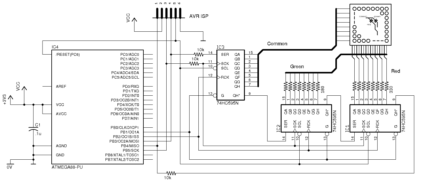
Schematic of SPI experimental target (HC595 supply pins, by-bass capacitors are not drawn)
The main MCU is ATmega88(V). It is clocked by internal RC 8MHz divided by 8. The supply voltage is 3.0V from two AA batteries. Three HC595 forms a 24-bit shift register and its output is connected to a dot-matrix LED display through series registers (330Ω for red anodes, 180Ω for green anodes).
Note: In my target each LED forward currents are designed as 4.0mA for red, 4.5mA for green. If all LED's in the same row are lit, the HC595 which is connected to common cathodes (IC3) will have to sink current of (4.0 + 4.5) x 8 x 2 = 68mA. The maximum current rating for supply pins of 74HC595 is 70mA, therefore the software must take care that none of two rows are driven at same time.
As designed earlier, MOSI is connected to SER input, and SCK to SRCLK clock. The display will be controlled well without MISO, but it is wired to the last bit of the shift register (IC1, Qh') to test SPI functions. HC595's output enable inputs are connected to Port output, PB1. That allows the software to switch off all LED's without clearing the shift register value.
AVR ISP flash programming feature is using MOSI, MISO and SCK pins. Some kind of isolation is required to avoid conflict between AVR programmer and target hardware. In the target schematic, simple isolation is done by series 10k&Omega resisters to avoid interference to the programmer. In addition, HC595's clear inputs are connected to the /RESET line to prevent unwanted target operation when ISP programming is on-going.
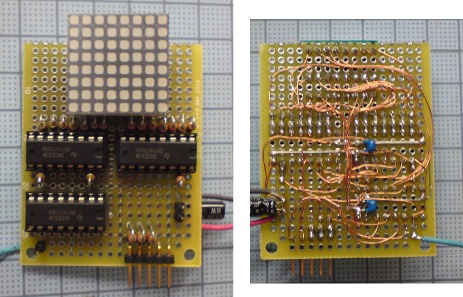
LED display daughter board (Top) / (Bottom)
I built up a daughter card to wire the dot-matrix LED display on universal PCB, and connected it to bread board where the main AVR ATmega88 is mounted. The picture shows top and bottom view of the daughter board.
Software
Overview
The following is the structure of the application software. Everything is written in a file as it is very short.
- Timer interrupt
- Count up ticker, and select the LED line to drive.
- Get the bit patterns for red and green LED's.
- Make the bit pattern for common cathode lines.
- Send "red", "green" and "common" data through SPI.
- main function
- Initialize ports, SPI, timer interrupt and variables.
- Enable interrupts.
- Infinite loop (do nothing)
In the application, timer0 interrupt is enabled with the interval of approx. 2mS to select a horizontal LED line and send 8bit data for each red/green/common lines through SPI. Data for common cathodes is logically inverted because it is connected to LED cathodes. After sending out data to SPI, control /OE line to switch off all LED before latch operation by /SS signal in order to drive the single LED line correctly. Consequently, all LED's are scanned every 2mS x 8 = 16mS, i.e. 60fps, which is fast enough for human eyes.
All source code (for avr-gcc)SPI functions
I used this source code for SPI functions almost same with ATmega88's datasheet examples. The SCK clock is set to f_osc/4 = 250kHz (4µS periods), and it takes around 32µS for 8 bits, and 96µS for 24 bits (1 line) data transfer. Because the total amount of waiting time is so small, the software is detecting SPIF flag (SPSR register) for waiting the finish of byte data transfer and doesn't use SPI interrupt.
void spi_init(void) {
  // SPI settings
  // Master operation, clock mode = 3, f_sck = f_osc / 4
  // (disabled SPI interrupt, data order = MSB first)
  SPCR = _BV(SPE) | _BV(MSTR) | _BV(CPOL) | _BV(CPHA);
}

void spi_begin(void) {
  // set /SS = low to select SPI slave device.
  PORTB &= 0b11111011;
}

void spi_end(void) {
  // switch off LED by /OE = high,
  // set new data by /SS = high,
  // and then turn on LED by /OE = low
  PORTB |= 0b00000010;
  PORTB |= 0b00000100;
  PORTB &= 0b11111101;
}

char spi_send(char cData) {
  SPDR = cData;
  while (! (SPSR & _BV(SPIF))) {
    ;  // wait for SPIF flag to be set
  }
  return SPDR;  // return data from SPI slave
}
|
Result
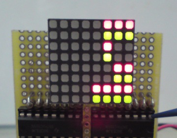
Result of display

Result of display
| Red (led_pattern_red[]) | Green (led_pattern_green[]) |
0b00000111, 0b00000110, 0b00000100, 0b00000001, 0b00000011, 0b00000101, 0b00001111, 0b00010001, |
0b01100111, 0b11110110, 0b11110100, 0b01100000, 0b00000000, 0b00000000, 0b00000000, 0b00000000, |
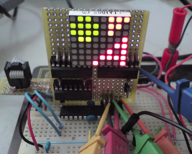
The picture shows the displayed result by the source code above. It is driving red and green LED's according to the test bit patters. (The constant tables, led_pattern_red[], led_pattern_green[], in the begging of source code include LED bit patters. The LED segments lit orange when both red and green elements are turned on.)
Waveforms observation
The following picture shows waveforms of main signals observed by a logic analyzer. A falling edge of /SS signal triggers the sampling. It shows that MOSI (master output) signal is changing on falling edges of SCK. Also it presents HC595's shift operations are made on rising edges by observing the output of shift register = MISO signal.
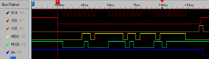
SPI signal waveforms
It takes around 40µS for 8-bit data transfer and 120µS for 24 bits. In former calculation, 32µS is required for 8-bit transfer, but some more time is added up because of function-call overhead. To send bytes faster without intervals, the functions of spi_begin(), spi_send() and spi_end() need to be combined into one so that three bytes are sent to SPDR register continuously.
Reading SPI input
It is not necessary for the application to read data from SPI, but as an experiment of SPI let's try it.
This small modification in source code is made to read back red pixels from even rows (0, 2, 4, 6) and write it to green pixels in next rows (1, 3, 5, 7).
| Original |
|---|
// SPI transfer (24 bit) spi_begin(); spi_send(red); spi_send(green); spi_send(row); spi_end(); |
| Modified |
  spi_begin();

  if ((led & 0x01) == 0) {
    // even rows: write test patter to red, turn off green
    spi_send(red);
    spi_send(0);
  } else {
    // odd rows: turn off red, read back red pixels from the previous row
    green = spi_send(0);
    // turn on green with the read data
    spi_send(green);
  }

  spi_send(row);
  spi_end();
|
The picture shows the result of modified software. It presents that the MCU is reading the same data (green) with the byte written into previous rows (red).
Note: Actually this direct wiring between MOSI input and Qh' output is not desirable because both shift operation (HC595) and sampling operation (MISO) are working on the same rising edge of SCK as observed in the waveform. Strictly speaking, it is necessary to insert some logic to provide half-clock delay to HC595 serial output before sampled by MISO.
Summary
About 74HC595
ATmega88 AVR SPI has flexible settings for clock and data timing and I could reduce the number of parts to connect HC595. 74HC595 (and 74HC family) is fast CMOS and has wide range of operating supply voltage from 2 to 6 volts. It is very useful to expand microcontroller ports to drive display or other devices that require many signals.
The demerit of HC595 is its current rating when using it as an I/O port. When considered the maximum number of LED to be lit, I could not allow large current to LED, and the result of display was rather dark (especially for green pixels). It may need to add current drivers to HC595 outputs or use AVR I/O port pins to sink common cathode lines.Other
For better graphic presentation by LED display, the application may need to adjust the brightness of each colors. The application in the article is using timer interrupt to scan LED lines and it would be possible to control brightness by applying PWM outputs to them. I'd like to improve the display quality if I have some opportunity.
Reference
- ATmega88 datasheet
- 74HC595 datasheet
You can read ATmega48/88/168 datasheet from Atmel site.
→
Atmel Products - AVR Solutions - ATmega88
The description of SPI is shown in chapter 18.
This is the page of the device made by Texas Instruments.
→
Flip-Flop/Latch/Register - Shift Register - SN74HC595 - TI.com
Conclusion
Many MCU have serial interface as peripheral like SPI, USART and I2C to exchange data. All of the are working with other device and we need to design not only internal operation of MCU but also whole system behavior. I could say that serial interface has exciting elements that other internal modules like timer or port don't have.
In the article I constructed simple system with AVR as an SPI master and single SPI slave device. It was very good for me to understand basic operation of SPI interface. I'd like to explore other system setup, for example, using AVR as an SPI slave, or other serial interface like USART or I2C.
Back to index