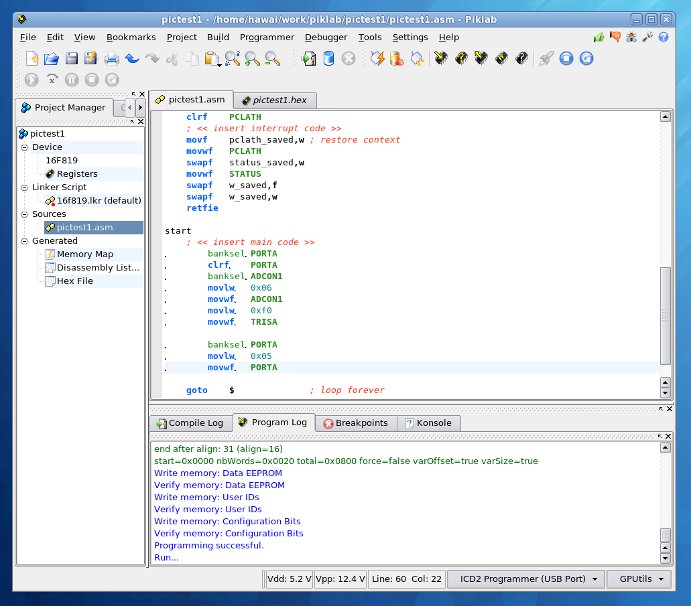
 I had a small try on "piklab", development environment for PIC microcontrollers on Linux. I could say that it is "MPLAB experience on Linux".
I summarized this article to introduce piklab, as the result was much better than I expected.
In the article, I'll explore installation of piklab, using gpasm assembler and sdcc compiler, building and download a small software, and basic debugging functions. Also making the target board to demonstrate simple LED display circuit by PIC16F819 controller as the main device.
About piklab
piklab is tool suite including GUI-based IDE for PIC/dsPIC microcontroller development on Linux. It is designed to be used like MPLAP which is provided by Microchip, and most users would be able to work on it without training much time. piklab is free and open-source software and licensed under GPL.
The home page of piklab is ...
here.

PIC development environment
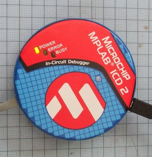
ICD2
There are several types of PIC programmers available. I'm using genuine ICD2 because I thought it would have less troubles and I'd be able to get helpful information on internet.
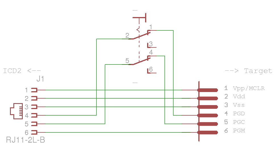
ICD2 has an RJ-11 6-wire connector for ICSP programming. I prepared a simple adapter to connect ICSP lines to target boards.
The adapter has a toggle switch to completely disconnect ICSP signal lines (PGC/RB6, PGD/RB7) from target borads. I'm thinking about smarter circuits by using electornic switching devices although the current method has no trouble and such improvement may not be necessary so soon.
Please refer to piklab support information about other PIC programmers.
The list of supported pic mcu's are shown in "Supported device" in piklab site. Note that debugging with some devices is not supported even though programming them is supported.
MPLAB
I prepared MPLAB environment on Windows XP. I utilized its firmware directory later in this article, and it would be good if you have MPLAB ready for reference use. It seems MPLAB works on WINE environment, but not tested in the article.
I skip detail explanation about MPLAB as there are plenty of good reference on internet.
Installation
In this article Fedora 12 is used as PC Linux platform. All software programs are installed by using official Fedora repository. I believe there is no big difference in other version Fedora or Ubuntu.
- gputils
- SDCC
- piklab
This package installs PIC assembler and related tools.
The version was 0.13.7 beta. (shown with "gpasm --version")
The homepage of gputils is here: http://gputils.sourceforge.net/.
This package installs C compiler that supports small microcontrollers like 8051, Z80 etc.
The version was 2.9.0. (shown with "sdcc-sdcc --version")
The homepage of SDCC is here. http://sdcc.sourceforge.net/.
Installed piklab simply by choosing from repository.
The version was 0.15.9です. (shown with "piklab --version")
After installation is completed, you can start piklab from "Menu" > "Application" > "" > piklab. The snapshot of piklab is shown in the left.
Setting piklab
Start piklab first time and make proper settings.
Setting Toolchain
This set up for assembler and C compiler for build your projects.- setting gpasm
- setting sdcc
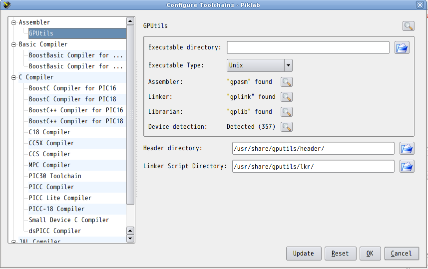
Open the setting dialog from piklab menu: [Settings] -> [Configure Toolchains...], and then choose [Assembler] - [GPUtils] item.
No special setting is necessary here. Just to check if piklab has found all of "gpasm", "gplink" and "gplib" commnads.
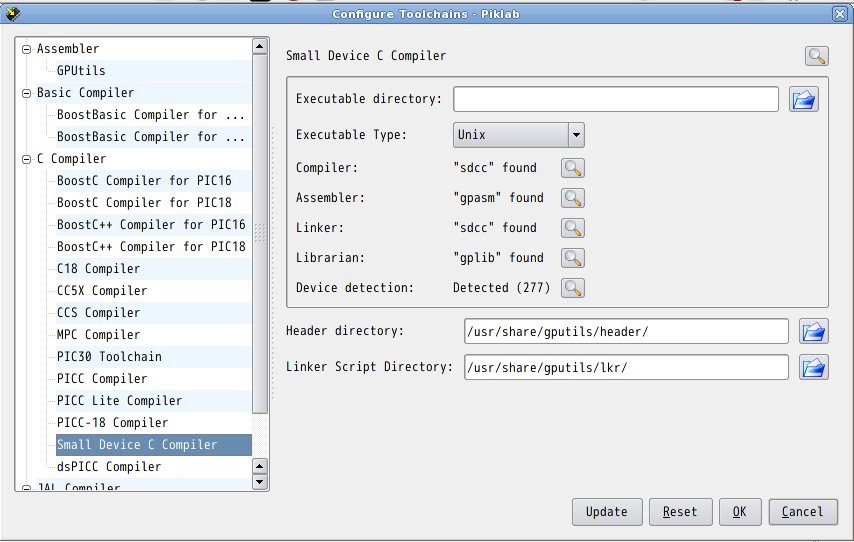
sdcc project seems to have changed its executable program name, and you need to specify "sdcc-sdcc" instead of just "sdcc". Piklab sdcc setting dialog, however, doesn't allow change of program name itself. This time I avoided errors ("sdcc not found") by making a link to sdcc-sdcc like following.
$ su
# cd /usr/bin
# ln -s sdcc-sdcc sdcc
# exit
After the procedure opening again piklab dialog from its menu: [Settings] -> [Configure Toolchains...], then choose [C Compiler] - [Small Device C Compiler]. You'll see that piklab has found sdcc.
setting ICD2 programmer
- setting port (USB)
- specify firmware directory
- About access rights on USB/ICD2
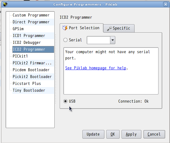
First, connect ICD2 to PC. Open dialog from piklab menu: [Settings] -> [Configure Programmers...] and choose [ICD2 Programmer]. In [Port Selectoin], choose [USB] as the port and confirm its status says "Connection: Ok".
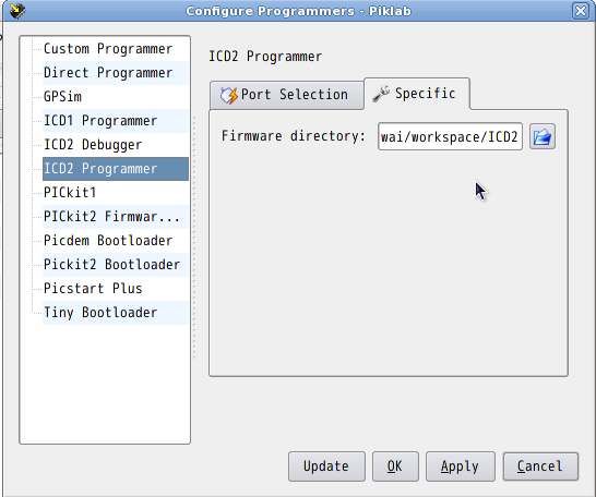
From MPLAB installed on Windows xp, copy firmware folder (by default, it should be C:\Program Files\Microchip\MPLAB\ICD2) and its content into some good place on Linux PC. In [ICD2 Programmer] dialog and [Specific] tab, specify the firmware folder for [Firmware directory].
If your Linux system doesn't permit your write access to USB ports (or serial ports), piklab cannot communicate with any programmer or debugger conntected to your PC. In that case piklab will put out an error of "Connection: Error", and you need fix your system settings.
First you can check if your ICD2 is correctly connected on USB bus.
$ lsusb
Bus 005 Device 001: ID 1d6b:0001 Linux Foundation 1.1 root hub
Bus 004 Device 001: ID 1d6b:0001 Linux Foundation 1.1 root hub
Bus 003 Device 002: ID 04d8:8001 Microchip Technology, Inc. ICD2 in-circuit debugger
Bus 003 Device 001: ID 1d6b:0001 Linux Foundation 1.1 root hub
Bus 002 Device 003: ID 062a:6301 Creative Labs
Bus 002 Device 002: ID 04d9:0022 Holtek Semiconductor, Inc.
Bus 002 Device 001: ID 1d6b:0001 Linux Foundation 1.1 root hub
Bus 001 Device 001: ID 1d6b:0002 Linux Foundation 2.0 root hub
In the example above, you can see the connected ICD2 is identified as "Device 002" on "Bus 003". It means ICD2 will be accessed through the device file of: /dev/bus/usb/003/002. Next, let's check the permission setting.
$ ls -l /dev/bus/usb/003/002
crw-rw-r--. 1 root root 189, 257 2010-04-21 13:06 /dev/bus/usb/003/002
This result tells that the device file is permitted R/W access to the group of "root", not to everybody. Now you can join the group "root" to talk through the device file. The permitted group may be different from system to system. It may be "uucp", "lp", "root" etc.
You can join any group by Linux administrative tool: from menu, [System] -> [Administration] -> [Users and Groups] (if you are using Fedora 12 English desktop).
setting ICD2 debugger
Setting ICD2 debugger is similar to ICD2 programmer.
- setting port (USB)
- specify firmware directory
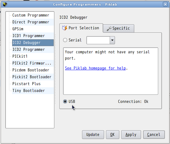
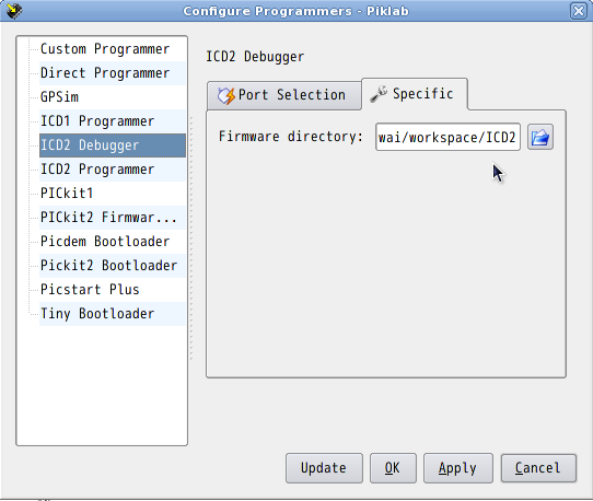
First, connect ICD2 to PC. Open dialog from piklab menu: [Settings] -> [Configure Programmers...] and choose [ICD2 Debugger]. In [Port Selectoin], choose [USB] as the port and confirm its status says "Connection: Ok".
From MPLAB installed on Windows xp, copy firmware folder (by default, it should be C:\Program Files\Microchip\MPLAB\ICD2) and its content into some good place on Linux PC. In [ICD2 Debugger] dialog and [Specific] tab, specify the firmware folder for [Firmware directory].
Connect to ICD2
Select [ICD2 Programmer] from [Project Manager] in the left pane. And then from menu, connect by choosing [Programmer] -> [Connect].
At this point you'll encounter errors like "low Vcc" or "Device ID" because no target board is connected. It will disappear after a target board is ready for programming. Let's continue.
The target spec
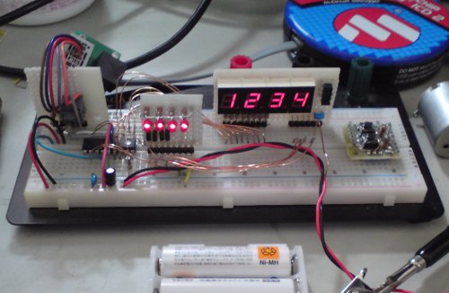
Now we start preparing the target board and programming software. My first target circuit is built on solderless breadboard. The main MCU is pic16f819 which I had in my part box. In this article, I touch upon I/O port and timer module to control LED display.
Target circuit
This is the schematic used for piklab testing (Series resistors to LED are all 1kΩ. Other resisters are 10kΩ). Four digits of 7-seg LED's are wired to be lit dynamically by shape of characters from Port B (RB0..7) and selection of digits from Port A (RB0..4). To be simple, digit select drivers are implemented with digital transistors. The system clock is set as low as 4MHz because it reduces the number of parts and it is safe to run on breadboard. The operation is rather slow with this clock setting, but instead, it will work with lower Vcc, like two AAA batteries.
Target software
By using timer interrupt the software selets 7-sed LED digits to light them up with each characters sequentially.- interrupt
- restart TMR0
- count up ticker
- select next 7-seg LED to drive
- output its character shape to the LED
- main
- initiallize ports, timers, system clock and watchdog
- initiallize ticker and LED buffers
- set up TMR0 interrupt and enable it
- main loop
- convert ticker value to decimal digits
- write decimal digits LED buffer
- repeat main loop eternally
The feature is very limited because this article is mainly for explanation of development/debugging with piklab. To make something useful (like a clock or counter) with this circuit you may need to add key input and design man-machine interface.
Create project (gpasm)
New project
First, create a new project using assmebler.
From piklab menu launch project wizard by selecting [Project] -> [New Project...]. And then fill necessary information like following:
| Basic Settings: | ||
|---|---|---|
| Name: | Name of your project. | |
| Directory: | Directory where the project is created. | |
| Device: | PIC MCU name for the project. example:"PIC16F819" | |
| Toolchain: | Toolchain for the project. Herein choose "GPUtils" to use assmebler | |
| Programmer: | Programmer for the project. example:"ICD2 Programmer" | |
| Source Files: | ||
| Specify the source files that your project will initially have. | Choose "Create template source file." to arrange template files. | |
Writing source code
Using piklab built-in editor, change config bits around the top of the source file so that it will fit to the target configuration. And then write up inside of the interrupt handler and the main function.
This is the completed (not all features are ready) source file.
Build the project
Now build the project with the written-up source file after saving it. From piklab menu, start building by selecting [Build] -> [Build project]. It soon will complete with downloadable binary file when "Success" message is printed.
Download and run
Connect to the programmer by selecting [Programmer] -> [Connect]. Piklab will check supply voltage and device id from the connected target board.
From piklab menu choose [Programmer] -> [Program] to download the binary. After download is completed, choose [Programmer] -> [Run] to release the taget from reset condition, then the target starts.
That's the end of the explanation how to create assmebler project. The example source file can be built but not completed because it is a torturous task for me to write longer source by using PIC assembler... Now allow me to proceed to the topic of C-compiler.
Create Project (C compiler)
New project using sdcc
First, create new project using sdcc.
From piklab menu, choose [Project] -> [New Project...] to launch project wizard. Fill in following information.
| Basic Settings: | ||
|---|---|---|
| Name: | Name of your project. | |
| Directory: | Directory where the project is created. | |
| Device: | PIC MCU name for the project. Example: "PIC16F819" | |
| Toolchain: | Toolchain for the project. Herein choose "Small Device C Compiler" | |
| Programmer: | Programmer for the project. Example:"ICD2 Programmer" | |
| Source Files: | ||
| Specify the source files that your project will initially have. | Choose "Create template source file." to arrange template files. | |
Writing C source code
The following is my example of C source code for the target. The final executable binary file is rather big because I considered nothing about efficient memory usage. The great thing is that it was quite easy to write in comprehensive C language. It also supports inline assmebler code, and it is better for me than using only either of assmebler or C compiler.
Build and run
Completely same with assembler project. Just connect to the programmer and download executable binary, and run.
Usually you need to test and debug the software before it brings you expected result. As next step, I'd like to explore some debugging features of piklab.
Debug
In this section I'd like to try piklab debugger's features. Piklab project says its debugging functions are still on development, but as far as I checked, its basic functions are working well enough to investigate causes of bugs. For small hobby projects it would be sufficient in most cases.
Connect ICD2 as a debugger
Select [ICD2 Debugger] as the programmer in the left pane of [Project Manager]. Note that piklab provides debug function to limited devices even if it supports programming. See piklab homepage for details.
Turn on DEBUG_ON bit
Add "DEBUG_ON" in the configuration word around the top of the source code. After building the project, connect to ICD2 debugger.
Set a breakpoint
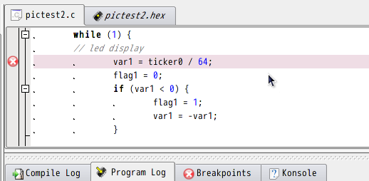
A test run with a breakpoint. Move to the line of souce code where you want to break, and set a breakpoint with right-click menu. After starting the target, MCU will stop if the specified line is executed.
Watch variables
You can use watching feature just select variables from left pane of "Watch". Each time MCU stopps, the watched variables are updated with its new values.
Step execution
If you choose step execution command when MCU pauses, the program executs next instruction and stopps again. It appears that piklab perform step execution on assembler instruction basis, and you may have to press several times to step forward to next line of C source code. In some cases it is better to set up a new breakpoint.
Inspect generatetd code
Piklab can show you generated assembler code from sdcc source file easily. Move to the line you like and look into its assembler code by right-click menu [Show disassembly location].
Note
Precaution
If your target configuration utilizes MCLR pin as general purpose I/O, piklab cannot hold MCU in reset condition after download, therefore MCU starts immediately. In that case you need to take care of ICSP-related pins (including MCLR) so that it won't interfere other target features if those pins are used as I/O pins.
Header file and constants for registers
Sdcc may use different identifiers for MCU register names that other C compiler defines. Those symbols are defined in the header files. If you encounter indetifier or definition errors, you may want to check header file content for the device.
Header files are in /usr/share/gputils/header (Fedora12).
Control from command line
Sometimes character based UI is quick and useful, for example, when you just want to download binary file. The following examples may be useful for such purposes.
- (sdcc) Compile single source file sdcc-sdcc -mpic14 -p16f819 pictest.c
- (piklab) Connect to the programmer piklab-prog -c connect -p icd2 -d 16f819 -t usb
- (piklab) Download compiled HEX file piklab-prog -c program -p icd2 -d 16f819 -t usb pictest.hex
- (piklab) Reset and restart the target piklab-prog -c run -p icd2 -d 16f819 -t usb
Finally...
PIC microcontrollers give us plentiful device lineups with abundant supply, low price and good reference books in Japan. With those merits a lot of hobbists are enjoying DIY projects with PIC MCU. I think PIC MCU is a good choice in many cases because of its wide variety of peripheral features to optimize cost effectiveness.
Small scale MCU like PIC is very practical and useful because you can quickly build up your projects or prototypes with less money and efforts. To maximize its merits, it is always important to shorten learning and preparation time for development. C compiler usage is very helpful when you need to quickly develop with new devices. Piklab, sdcc and gputis are all free and open source software tools working on Linux, and no reason to avoid them when you try PIC development on Linux. Thank you to everyone who works for the excellent software projects!!
Back to homepage


